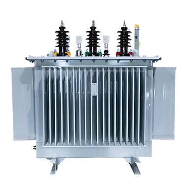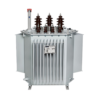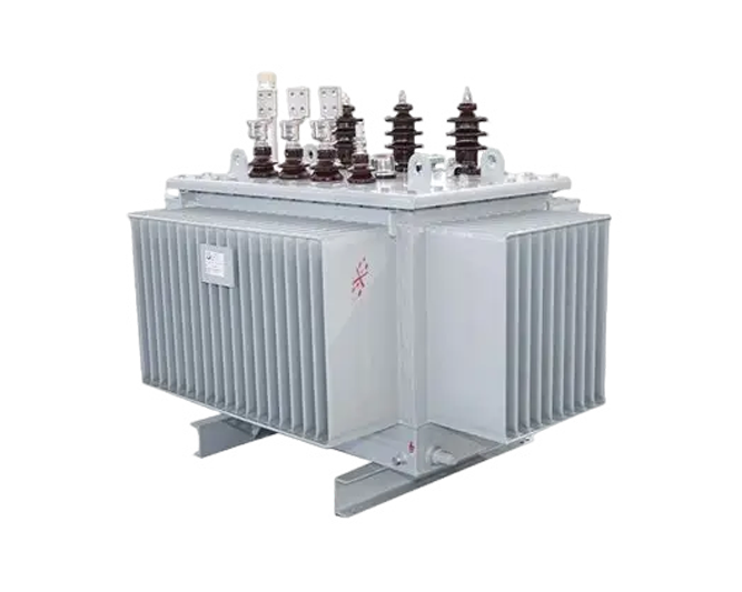
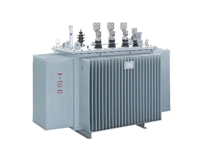
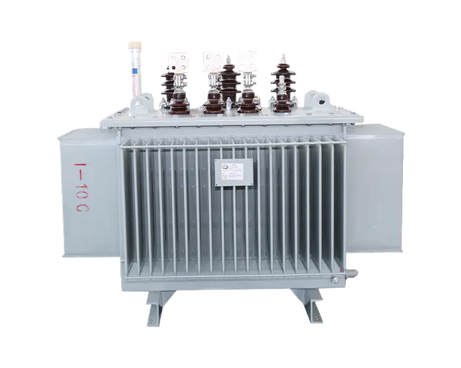
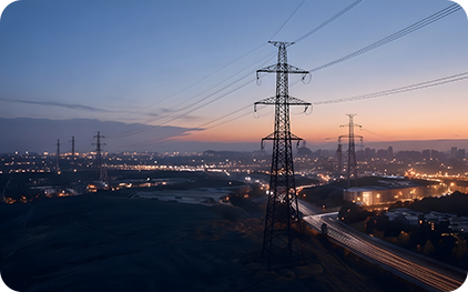
This product is a new generation of energy-saving and environment-friendly transformer. It adopts an amorphous alloy core manufactured by rapid solidification technology, in which metal atoms are arranged disorderly. Featuring better magnetization and demagnetization performance than silicon steel, it can significantly reduce no-load loss of the core and is known as a “green material”. Widely used in rural power grids and other low-load areas, it is one of the key equipment for energy conservation and emission reduction in power transmission and distribution networks.
![]() High efficiency
High efficiency
![]() Low noise
Low noise
![]() High reliability
High reliability


Eco-friendly design
Amorphous alloy transformers cut carbon emissions drastically with low production energy use and minimal running loss, leading green energy innovation.
Small size and light weight
With superior magnetic permeability, our amorphous alloy transformers achieve smaller size and lighter weight, bringing convenience to handling and installation.
Strong overload capacity
Excellent overload capacity allows the transformer to withstand large overload current in short time, ensuring safe and stable operation.
Low temperature rise
With low loss and low temperature rise, the transformer ensures stable operation, higher reliability and longer service life.
Strong adaptability
Strong adaptability to harsh environments including high temperature, high humidity and high altitude, ensuring stable operation under complex conditions.
Intelligent options available
Strong adaptability to harsh environments including high temperature, high humidity and high altitude, ensuring stable operation under complex conditions.
Future-oriented
With advancing tech and lower costs, amorphous alloy transformers will see wider use as a futureproof choice for energy-saving power systems.