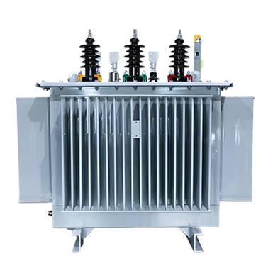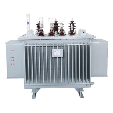
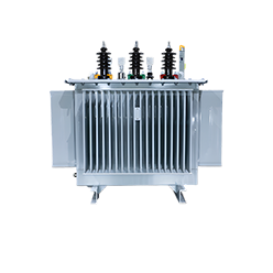
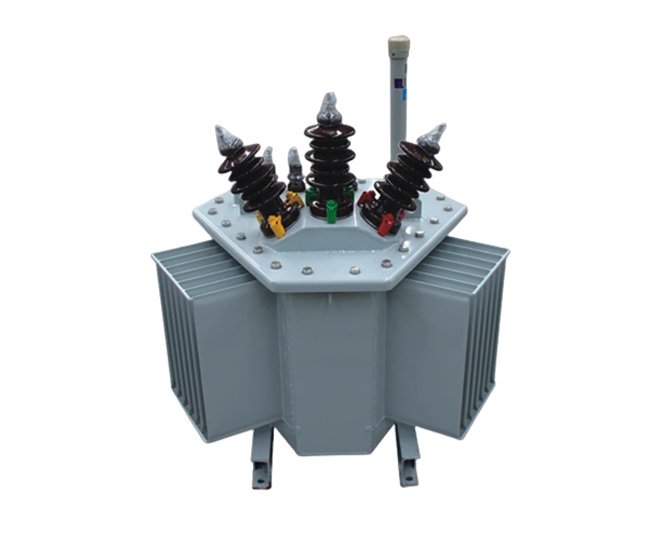
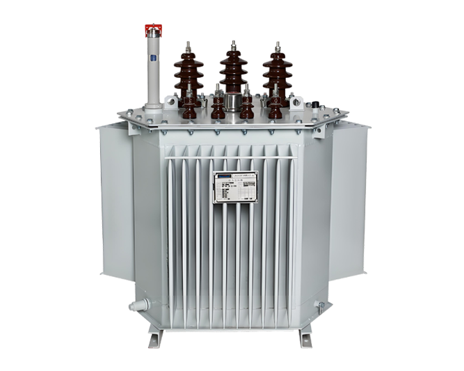
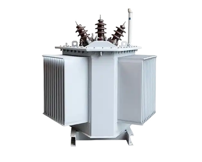
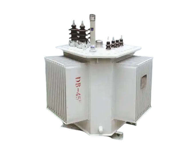
S11 Oil-Immersed 3D Wound Core Transformers adopts three-dimensional wound core technology with symmetrical three-phase structure and balanced magnetic circuit. The utilization rate of silicon steel sheet is nearly 100%, featuring no joints, low magnetic reluctance and high stacking factor. No-load loss, no-load current and noise are reduced by more than 10dB, making S11 Oil-Immersed 3D Wound Core Transformers highly efficient, energy-saving and widely applicable. S11 Oil-Immersed 3D Wound Core Transformers is an energy-efficient product.
![]() High efficiency and energy saving
High efficiency and energy saving
![]() Low noise operation
Low noise operation
![]() Oil-immersed cooling
Oil-immersed cooling


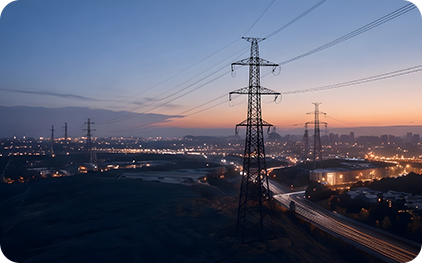
High reliability
Excellent reliability with superior insulation, strong anti-short circuit capability and stable performance in harsh working environments.
Eco-friendly design
Eco-friendly design with green materials and processes, meeting environmental standards and modern power system requirements.
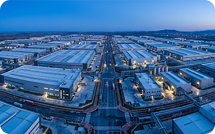
Compact structure
With compact wound core, it features energy-saving, small size and light weight, easy installation and space saving.
Easy maintenance
Oil-immersed structure enables easy inspection and maintenance, reduces operation cost and prolongs service life.
Strong short-circuit withstand capability
Strong short-circuit withstand capability with stable core & reasonable winding design, ensuring safe operation under high impulse.
Low temperature rise
Optimized oil cooling and core design ensure low temperature rise, enhancing reliability and service life of the transformer.
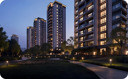
Strong adaptability
Excellent environmental adaptability, performing reliably in high temperature, humidity and high-altitude conditions for diverse power applications.
Good economy
High initial investment but remarkable long-term economy with high efficiency, energy saving and low maintenance.
Intelligent options available
Flexible intelligent integration option for real-time data monitoring, remote control and predictive fault analysis.

No.8, the 5th Diamond Rd, Zhengzhou New Materials Park, Zhengzhou City, Henan Province, China.

008613633842966

gridsales@eaglegrid.tech